Multiband Loop Antenna Project
by Gary Marbut, K7GMM
and Ty Marbut, W7TYY
Greetings Visitor,
In the article below, I’d like to describe the theory and the
mechanical build process for a 160m-long multiband loop antenna,
including its support system, tuning, and SWR analysis. The
goals of the project were to provide an optimized antenna for 40m,
80m, 20m, and all other HF ham bands, in that order of priority.
As a new ham (licensed in 11/13), I've been on a steep learning
curve.
Background and Mast Design
I was drawn into the ham world by my son Ty (W7TYY) who lives in
Portland, Oregon, and who though we ought to have a way to talk
independent of phone lines and the Internet. Ty set me up
initially with an Icom-707, an LDG Z-100 Plus tuner, and an inverted
V, center-fed dipole cut for 40-Meter.
For that setup, I made a mast base that bolted to the face of a
dormer on my geodesic dome, a base that would accept sections of
military surplus, nesting fiberglass tent poles for a mast.
These tent pole sections are about 4' long and allowed us to add
sections to gain elevation. This mast was originally guyed
three directions with nylon 550 cord, since replaced with stouter,
more UV-resistant material with less stretch. Since hanging
the inverted V dipole, the mast has also been topped by an Ed
Fong-style (WB6IQN) dual-band J-pole in PVC, which fit nicely
into the top section of fiberglass mast.
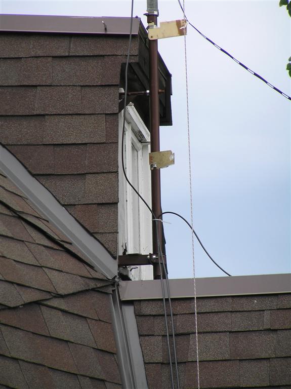
I originally designed the mast base to be tipped down. Tipping
it down proved to be impractical. However, this base has
served well so far. Here is the mast base that attaches to the
dormer of the house.
From the side
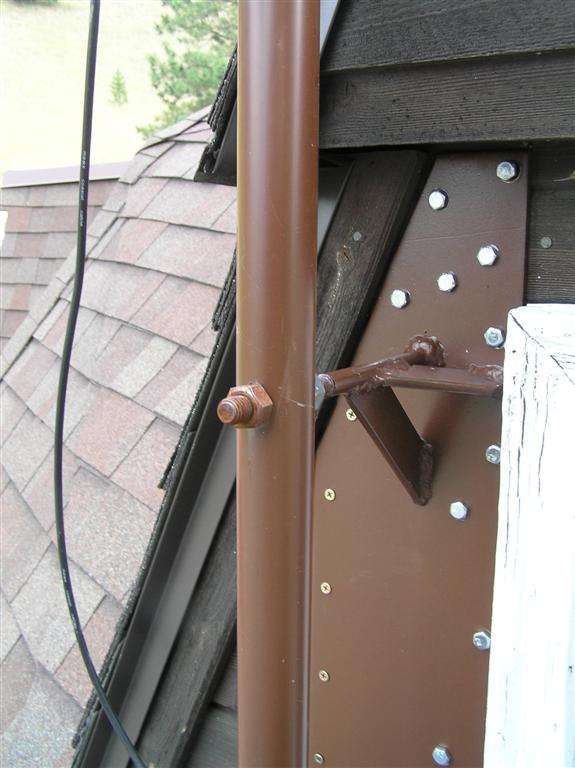
Top of front - pivot point for tipping
Bottom of the front - clamp here, pivot above
for unused tip-down
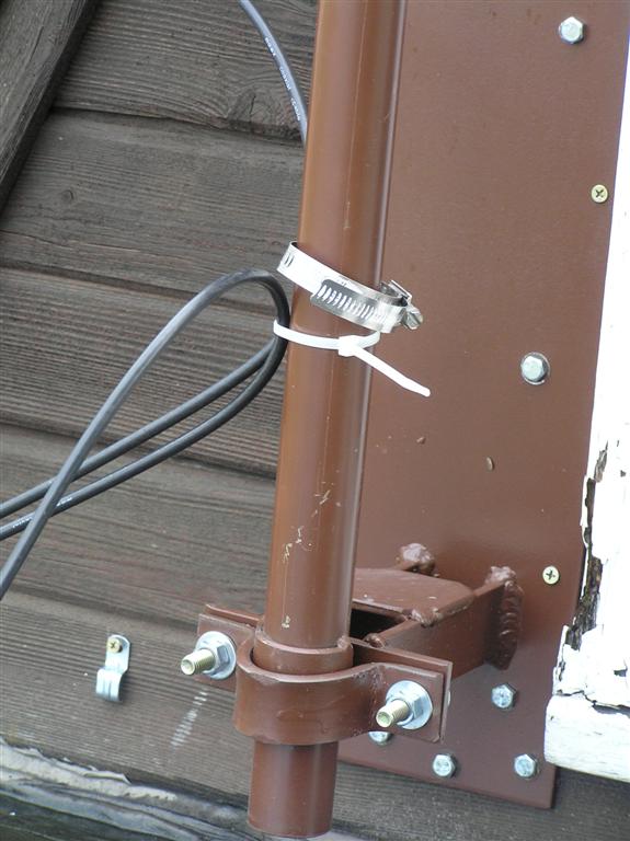
The whole base from the front
How the fiberglass tent pole sections fit to
the base
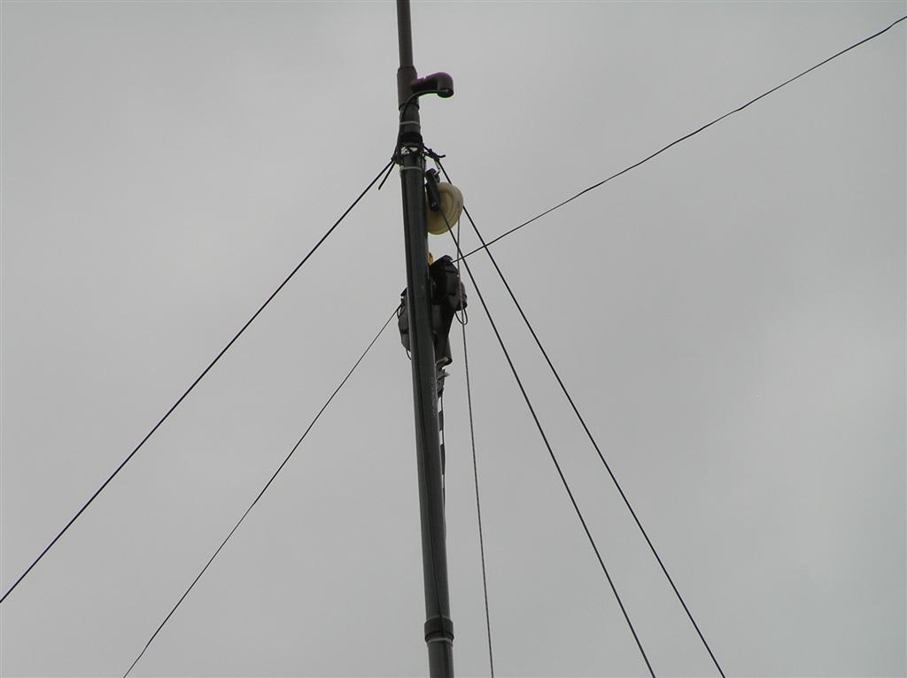
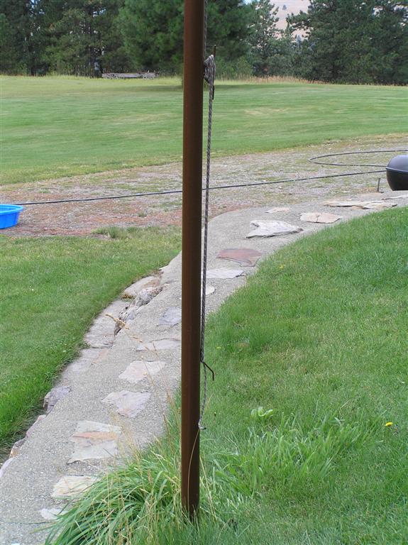
Looking up my mast. Three guys, two loop
lines, one lifting line for the loop feedpoint, and PVC on top
holding a J-pole for VHF/UHF.
Another view of the top of the mast with guys,
loop, feedpoint lift line, and PVC for J-pole.
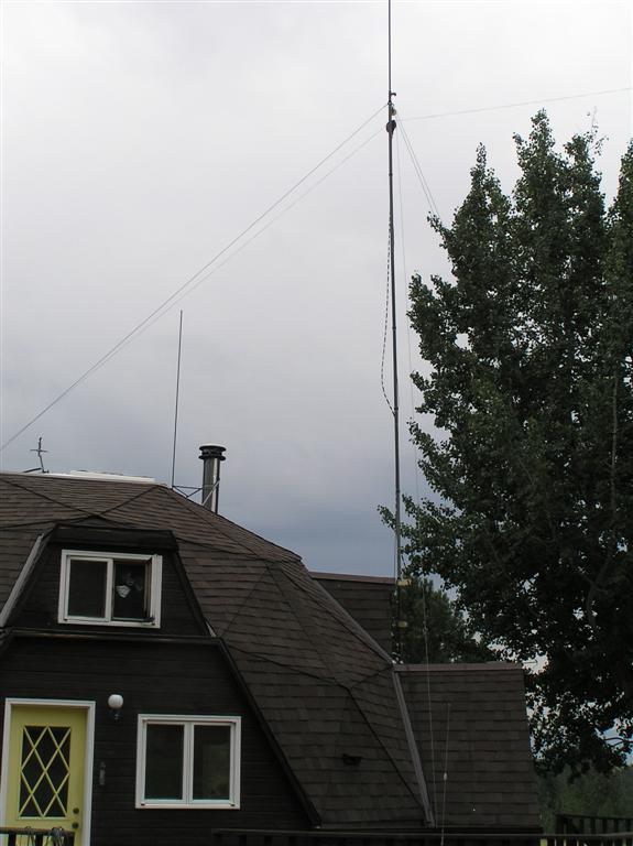
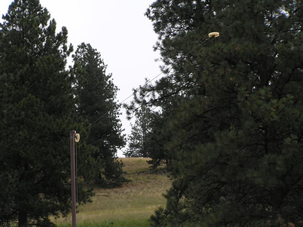
A more distant view of all of this
I transitioned from the inverted V to a G5RV and increased my commo
ability a lot, but I still couldn't tune 160M, and 80M and 10M were
difficult to tune. With many suggestions and encouragement
from Ty, I decided to replace the G5RV with a square loop.
That initiated a new learning curve. I would need four
corners, in addition to my existing mast. I have space on my
property, but no trees in the right places. I decided to make
my own corner posts.
The first problem was where to put the corners of the loop. I
wanted about 160 Meters of wire in the air. I guessed at where
the four corners would need to be to make this total, with some help
from Google Earth. One of my design criteria was to keep these
corners out of the area I mow so I wouldn't have to mow around them.
Supporting the Loop
The first problem was where to put the corners of the loop. I
knew I wanted to use the top of the mast as the feed point. I
also knew that more wire in the air was better, all else being
equal. So, Ty helped me use Google Earth to plot some corner
post locations for loops which would be resonant on 40m, as well as
other bands. Given the size and shape of the space available,
we landed on a 160m long loop, which we would design to resonate on
40m. We would get the added benefit for resonance on the top
bands (160m/80m), while really tailoring the performance of the loop
to be a 4-wave loop on 40m. A little math showed 20m, 15m, and
10m also being more-or-less resonant on the 160m of wire.
Ultimately, I chose the corners to provide for plenty of length,
convenience in mowing, and using a system for stringing the wire to
allow me to shrink the loop as needed for tuning.
I dug four post holes in the selected corner locations, about three
feet deep. I got a length of 2", schedule 80, black pipe
(comes 21'), and cut off four 2.5' sections. I set these in
concrete in the four post holes, plumbed them, and let the concrete
cure. I mixed sacks Quickrete in a five-gallon plastic bucket
for this, stirred with a crowbar. It took two 50-pound sacks
per hole (Tip: Mix only half a sack at a time.)
I also got four sections of 1 1/2" schedule 40 pipe, selected for
minimum needed strength and to slip-fit inside the 2" pipe set in
concrete. These come in 21' sticks also. Two feet from
the bottom of each of these pipes I welded on a stop, so they would
only slip 2' into the 2" pipe. I welded on cleats to secure
550 cord to, drilled the top ends and installed eye bolts, painted
the pipes, and put plastic caps on the top once the paint was dry.
Here are some pics of how the corners turned out:
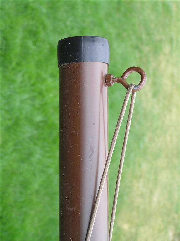
Here is how the top of each corner post was
treated
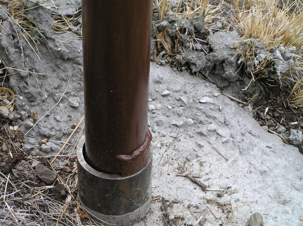
Here is how the bottom fits into the 2" sleeve
Notice the stop welded on the 1 1/2" pipe to
prevent it from slipping too far into the 2" pipe
Here you can see the cleats I welded onto the
pipe to secure the idle end of the 550 cord
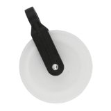
I hooked plastic clothesline pulleys to the top end of the 550 cord,
beyond the top eye bolt, to carry the loop wire.
I got these from Amazon.com at:
http://www.amazon.com/SYMMETRY-4-Inch-Plastic-Pulley-93314/dp/B00JRBNVUE/
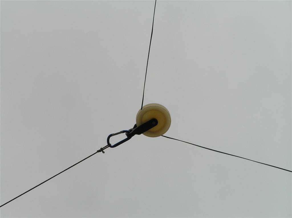
Installed, they look like this.
By shortening or lengthening the 550 cord holding the pulleys at the
four corners, I am able to adjust the loop size. The only
metal in the pulleys is the small axle.
To be able to tension the loop at a steady tension, I put another
pulley at the top of one corner for the 550 cord to pass through,
and hung a lead weight on the 550 cord. This lead weight
weighs about 15 pounds. This should allow loop expansion and
contraction with wind and temperature changes, but keep it at a
uniform tightness.
Here's the extra pulley at the top of one
corner to carry the 550 cord for the weight.
Here's the weight hanging near the bottom of
the selected corner. A bucket of rocks would work as well.
As I said above, I had plotted this loop on Google Earth
(below). The loop you see in this image is the plot without
any stand-off length from the corners, as described later - just red
lines corner-to-corner.
Here is the original plot. The feedpoint/mast is near the
middle of the west side, and using the standoff expansion (described
later) the west side ends up being effectively straight (rather than
the mild concave angle in this graphic).
Constructing the Loop
I'm a pretty mechanically-competent guy, but studying into the
electronics of this setup was a challenge. One of the first
big question was what wire to use. I'd need a lot of it on a
limited budget. Plus, the wire would need good tensile
strength, since the longest span would be just short of 200'.
It would need to be pretty tight to prevent excessive droop,
challenging my already-minimal height-above-ground.
Ty suggested Poly-Stealth antenna wire for this purpose, because it
is used in circumstances such as this by hams when tensile strength
is an issue. Poly-Stealth antenna wire has mostly copper
strands, but also contains steel strands to increase total tensile
strength and to reduce stretching. However, because it’s a
little less expensive (and maybe due to some nostalgia for my days
in the US Army), I ordered a spool of military surplus WD1A "commo
wire". This wire has two separately-insulated conductors and
is made to be used outdoors. Much like the Poly-Stealth, each
conductor is comprised of three steel strands and four copper
strands.
Here's what's left of the spool after running
the loop
Here's the label on the wire spool
Although the wire is not as thick as I'd like,
it is strong.
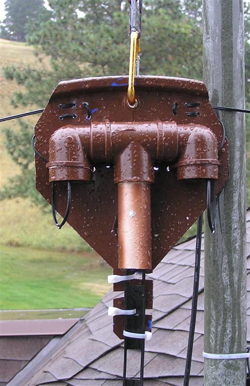
I decided to go with a homebrew feedpoint. It would have to
take the tension of a tight loop, it would need a weather-sheltered
place to make the ladder line/loop connections, it would need to be
non-conductive, able to carry the weight of the ladder line, and it
would need a lifting point. I'm only mildly embarrassed to
admit that I made the backing for the feedpoint out of the lid of a
Costco laundry detergent bucket. I put together a 1" PVC T,
two 90s, and a short piece of 1" PVC pipe to form the shelter and
separation for the leads. I secured them to the backing with
wire ties. I drilled holes in the backing to lace the loop
wire through to hold the tension, another hole for a lift point, and
more holes to support the ladder line with wire ties. A bit of
spray paint turned the blue and white mostly brown. Here's how
it turned out:
The bottom leg of the T is not glued so I can
pull it down to solder and heat-shrink
the ladder/loop connections, and then pull the connections into
the sides of the T.
When Ty and I first played out the wire for the loop, we measured it
carefully, marking the wire with white tape every 50'. So, we
knew for certain that the first installation was 612' of wire in the
air. It was not cut to that specific length. that's just
how much wire it took to make the circuit from the feedpoint, around
the corner posts, and back to the feedpoint. As we were
installing, a ham friend showed up to help. He recommended
that we feed the loop with 450-Ohm ladder line and a balun. He
happened to have both to loan, so the first testing was done with
612' of loop wire, 43' of 450-Ohm ladder, a 4:1 voltage balun, and
about 50' of RG-8X coax from the balun into my shack and to my LDG
Z-100 antenna tuner.
Using my MFJ-269 antenna analyzer, I was disappointed to learn that
the SWR across the HF bands was not at all what I'd wanted.
I'd seen all sorts of recommendations Online about the length of
wire for a 160-Meter loop, and none of the were 160 Meters.
The two most common suggestions seemed to be around 558' and 527',
to include 160m and to maximize the amount of wire in the air.
For our multiband loop (focused on 40m with bonus resonance on other
bands), the length would need to be about 536’ by calculation -
quite close to the recommendations for a 160m loop. However,
since it is a non-standard configuration, we decided to be very
conservative about cutting back, and instead to test several lengths
between the original 612’ and the mathematically-suggested lengths.
However, Ty pointed out that my loop (well, every loop) is unique
because of shape, height, wire, terrain and other factors. So,
we embarked on a process of cutting the loop shorter and shorter for
SWR measurement and tuning. Fortunately, relaxation of the
standoffs at the corners allowed progressive shrinkage of the
loop. The first cut was from 612' to 580'. SWR improved,
but not dramatically.
After that first cut to 580, a bunch of changes were made to the
installation. At every change, I measured and recorded SWR at
the top and bottom of all HF ham bands, and all "sweet spots" (I
defined as less than 3:1 SWR) from 1.8 to 30 MHz. It was
interesting to watch these sweet spots migrate as changes were
made. Many of the sweet spots were not within any ham band.
One suggestion was that I needed 63.9' of 450-Ohm ladder, instead of
the borrowed 43'. So, I ordered a 100' chunk of new
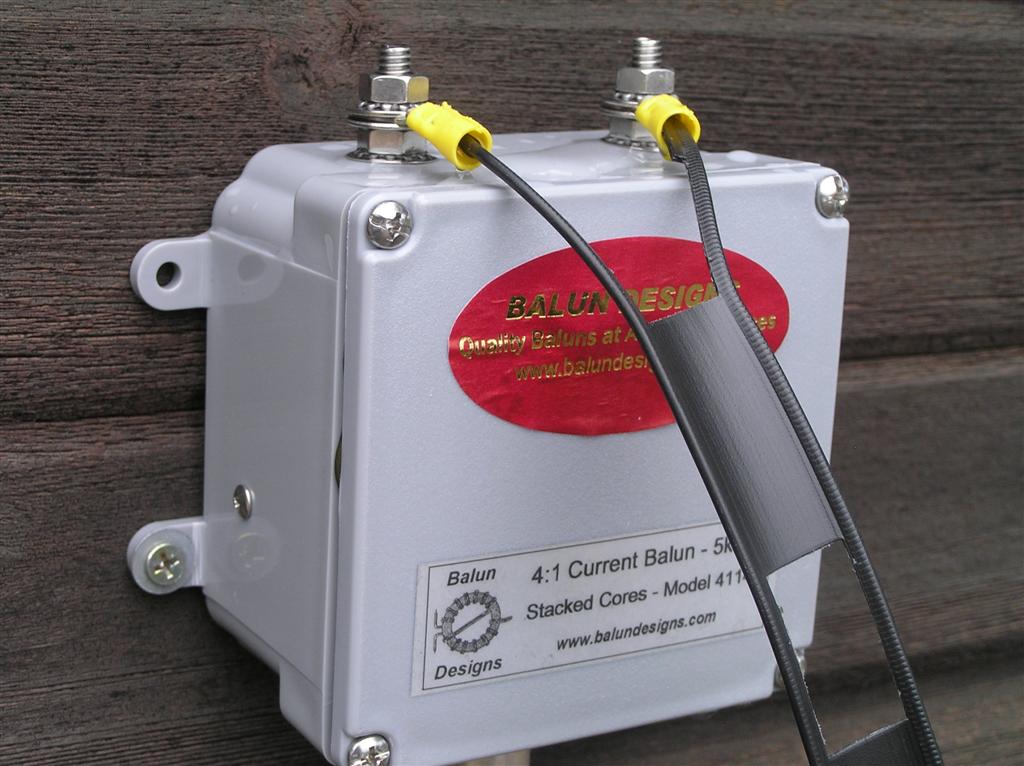
ladder. Another common suggestion was that I needed a current
balun rather than the borrowed voltage balun. So, I ordered a
4:1 current balun from Balun Designs.
Note that this is a feed setup for 40m, not for 160m. My
primary target was 40m, and also running enough ladder line to
accommodate 160m was going to be impractical and expensive.
So, I selected a length of ladder line suggested for feeding a 40m
loop, hoping that the autotuner would handle the difference at 80m
and possibly even at 160m. Most of what I had read about
ladder line feeding of loops said that multiples of half wavelengths
were best, so 63.9’ (½ wave on 40m) would be ideal for 40m, 20m,
15m, and 10m.
When the new ladder came in, I installed all 100' and did the full
SWR test with the MFJ-269. Then I cut the ladder back several
times, to several theoretically desirable lengths, ending at a
recommended 63.9'. At each step, I did SWR testing and
recorded results.
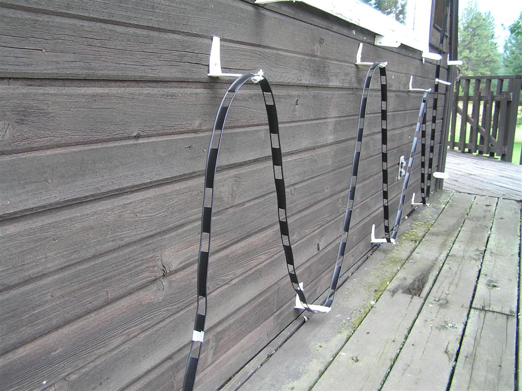
Feedline Routing
At this point, I had some extra length of the ladder line feeding
the loop, and needed to decide what to do with it. I had heard
that ladder line is very sensitive to other metal objects it comes
near or in contact with, including crossing over itself. In
fact, I didn’t even want to run the ladder line nearby or parallel
to itself, given the interactions I had heard of. So, I
decided to use non-conductive, L-shaped brackets to hold and route
the ladder line to take up the extra length along the exterior wall
of the house.
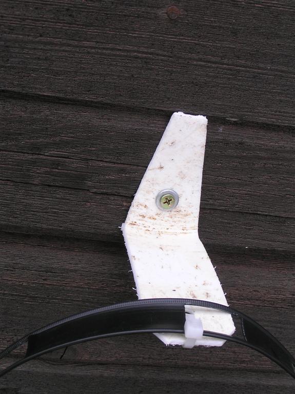
After scratching my head some, I made the needed L-shaped brackets
from a plastic, five-gallon bucket. On my table saw, I made a
series of cuts into the base of the bucket, about 1 1/2" apart, and
about four inches into the side and bottom of the bucket.
Then, I cut around the side of the bucket about 4" from the
bottom. It was then easy to cut these L-shaped sections loose
from the bottom of the bucket with shears. I drilled a hole in
one end of the resulting L for a screw, and in the other end for a
plastic wire tie.
This is what these brackets look like.
I tested them by putting them in my microwave to make sure this
plastic doesn't contain any conductive material. The test
piece stayed cool.
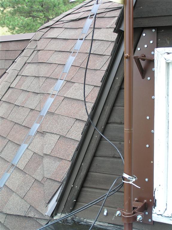
Here's how I used these brackets to route and
absorb the length of my ladder.
Then the new balun came, so I installed it and ran the full range of
SWR tests again.
The SWR kept improving, but was still not great. I replaced
the 50' of RG-8X with about 10' of RG-58A/U to make the run from the
new balun inside to my antenna tuner, just to reduce the length of
the coax and try to reduce any SWR readings that were just figments
of the coax. That alteration produced no changes, so I
concluded that the coax is not a problem.
My target bands for good SWR were 40M, 20M, and 80M (in that order),
but I wanted the SWR to be good enough that my tuner would tune the
loop in all the ham bands from 160M to 10M.
Tuning and SWR Analysis
One knowledgeable friend advised me to begin cutting the loop by 3"
increments, measuring SWR across all ham bands for each step.
NO WAY!! To relax the loop, lower the feed point, make a cut,
reattach the loop to the ladder, raise the feedpoint, re-tension the
loop, and test SWR across HF bands, took a full hour. At 3"
per cut and test, that would put me into the next ice age before
getting any definitive results.
So, at this point, Ty did some math to figure out how much loop
length we would need to cut to bring the loop meaningfully closer to
in-tune for 40m, and it appeared that we could take off 5’ at a time
without making more than about a 5% difference in the frequency of
resonance - that is, we could shorten by 5’ without going anywhere
near too far.
We also got more sophisticated about SWR tracking when we began
tuning the loop length. We entered more specific SWR data into
a spreadsheet so we could graph SWR and to forecast SWR numbers for
shorter loop lengths to meet my goal of good SWR on 40m, 80m, and
20m. In order to get data for this, we began shortening the
loop by about 6' at a time. At each cut, we'd record SWR at
the bounds of each target HF band (40m, 80m, and 20m), at the center
of each band, and above and below each band at a distance equal to
the distance from edge to center. This was a bit tedious, but
gave us a lot of data points. I ran the MFJ-269, and Ty
entered data points into his spreadsheet. Ty also wrote the
formulae to portray spreadsheet changes as graphs.
More importantly, we also tracked the nearest low point in SWR above
and below each target band, and this analysis proved to be the most
fruitful. There were low points of SWR a couple hundred
kilohertz below each target band. The prediction was that by
gradually shortening the loop, we would be able to track the low
points below each band as they moved up and into the respective
bands.
After we had cut the loop about five times and recorded all the
data, a pattern which matched the predictions began to emerge, a
pattern visible on the graphs from the spreadsheet. At each
cut, we'd get closer to a low point on the curve for SWR for 40M and
that low point would move up in frequency. The linear
progression predicted that if we cut the loop to get the best SWR
centered on 40M, a similar low point on the curve for 20M would be
at the top of that band, and at 80M the low point on the SWR curve
for that band would be near the bottom of that band. The
predicted loop length (predicted by extrapolating linear
progression) to optimize desirable SWR on 40M was 537' for the loop.
By that time we had the loop cut back to about 542'. So, we
decided to trust the spreadsheet graph and cut the loop to the
spreadsheet-predicted optimum of 537'.
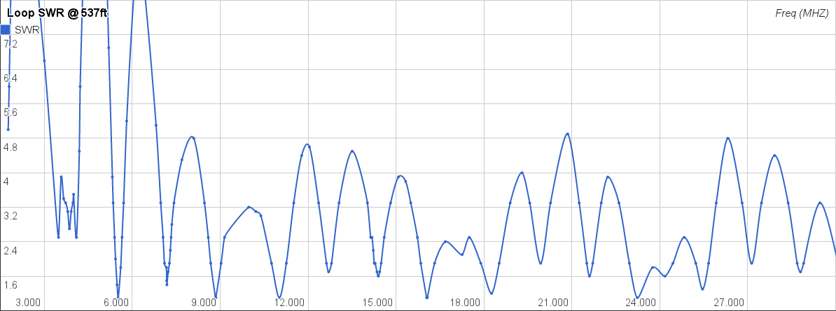
The SWR was definitely better at the 537' cut. SWR is below
3:1 all across 80M, below 2:1 across 40M, and below 2.5:1 across 20M
(actually <2:1 in the upper half of 20). My LDG Z-100 tuner
will now tune everything from 160M to 10M.
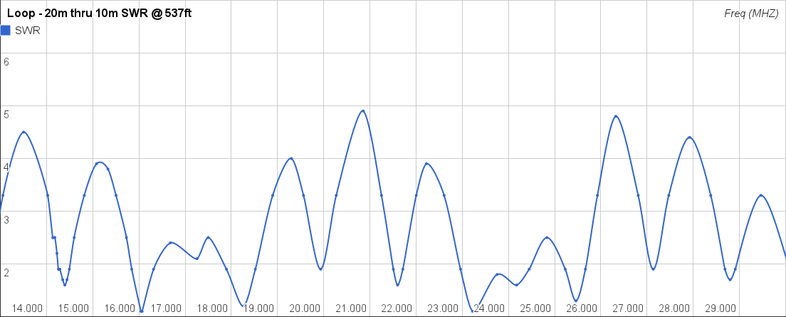
Here are some of the graphs we found useful:
Full SWR readout from 1.5mhz to 30mhz
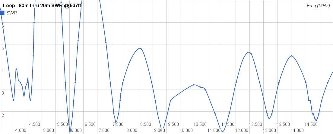
SWR readout from 80m-20m
SWR readout from 20m to 10m
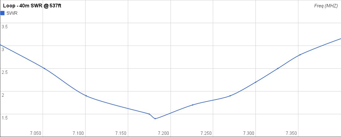
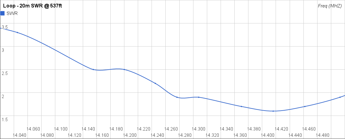
SWR in the vicinity of 40m (the primary target
band) with the loop cut to 537’
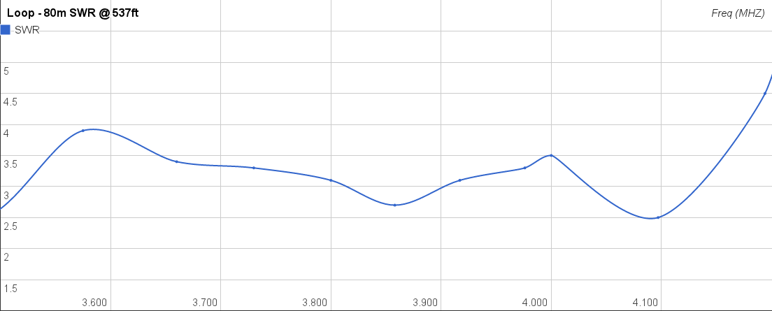
SWR in the vicinity of 80m
SWR in the vicinity of 20m
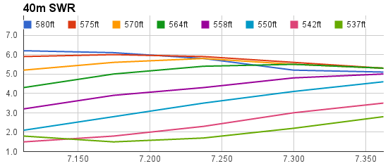
Several interesting patterns were also visible in the data that will
be valuable to others who are tuning their loops by changing the
circumference (especially multi-band or multiple-wavelength loops
such as this one). First, take a look at the SWR curves of the
different lengths of loop - all with 63.9’ of 450-Ohm ladder line
and a 4:1 current balun:
SWR curves in the vicinity of 40m. There
is a minimum SWR point (off the left side of the graph)
that winds up at about 7.175mhz, but which slowly moved up into
the band as we cut the loop.
The effect of moving the sweet spot up in
frequency is maybe more pronounced on 80m, a secondary target
band.
20m was also a secondary target, so minimum SWR
inside the band was slightly sacrificed for
minimum SWR inside the 40M band. Of course, it still tunes
quite easily.
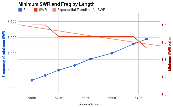
Another pattern of note was that as we brought the point of
resonance closer to the 40m band, its minimum SWR decreased, and the
bandwidth of the low point therefore increased. This is
presumably because the loop length was coming closer to matching the
40m-designed 63.9’ feedline.
As the frequency of minimum SWR approached the
design frequency, the minimum SWR also dropped.
The spreadsheet from which this data is drawn and which houses the
graphs is viewable
and downloadable here.
Final Dimensions
So, this seems like success. The current installation
is: 537' of military surplus commo wire loop, 63.9' of 450-Ohm
ladder, a 4:1 current balun, and about 10' of RG-58A/U coax from the
balun to the tuner. The loop is about 35' above ground at the
feedpoint, going to a minimum of 19' above ground on the corners (it
is actually a bit higher, because the feedpoint lifts the standoffs
at two corners).
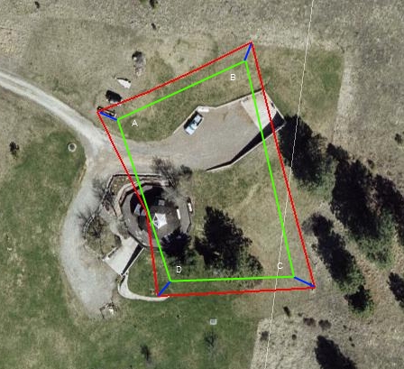
Here is the Google Earth graphic with the
corner standoffs (blue) added
and the reduced loop (green) drawn in (none to scale, but close).
The original plot, to the corner posts, is still red (as above).
Here are my refined best estimates of the loop sides lengths:
AB = 119'
BC = 175'
CD = 110'
DA = 133'
Total = 537'
Also, A-to-feedpoint is about 60' and D-to-feedpoint is about 73'.
Performance
So far, Ty and I have only operated the loop seriously maybe a dozen
times. The first major operating was the day we tuned the
loop, which happened to be during the North America QSO party.
We worked a couple dozen stations on 20m with ease, mostly around
the SW US, but also including Alaska and the midwest, so the
directions of the lobes of gain on 20m seem to be fairly dispersed.
Then, Ty parked it on a 40m frequency and I watched him handle calls
for 3 hours straight with no breaks until the end of the contest
(dolling out points - we did not submit a log ourselves).
Apparently the reports on 40m were 5/9 or better from everyone we
could reach, which included stations in every region of the country,
as well as Alaska and Hawaii. We concluded from this that if
there are multiple lobes of gain on 40m (driving the 160m loop as a
4-wave 40m), they are numerous enough and dispersed enough that we
don’t seem to hear any differences based on compass direction.
However, we did note more distant 40m contacts than I was used to
with the G5RV, and some specific areas where we got particularly
good signal reports, including Southern California and Texas, which
may indicate some specific lobes of gain.
We also made some contacts on the bands from 20m-10m, including a
few which spanned the Pacific (to NZ and JA) without much trouble.
Further Testing and Questions
A few questions about this loop remain. Any insights you have
about these questions is welcome.
Height - 20ft height was chosen mainly because of the length
that the sticks of 1 ½” pipe comes in. Although it would be
difficult to bring the height up more than another 10ft, it would be
interesting to know how raising the overall height would affect
tuning and (so far unplotted) lobes of gain. Would another 10'
of height be worth the effort?
Lobes - As mentioned above, we have no knowledge of the lobes
of gain from this antenna. Presumably, when operating on 40m,
there are lobes occurring at multiple compass bearings.
However, we don’t know how many of these lobes there are, and only
have a few ideas about which way any lobes are currently
pointed. The most we know about this is that contacts were
especially strong into Southern California and Texas during the
North America QSO Party.
Feedline - The length of 63.9’ of 450-Ohm feedline was
determined by equation, rather than by experimentation.
Although it would be impractical to run the ~128ft feedline that
would be prescribed for 80m, not to mention ~256ft for 160m, it
would still be interesting to know whether other feedline lengths
might provide lower SWR across the board.
Wire type - The commo wire used for this build is a little on
the light side, and is probably the minimum recommendable for my
100W. One question brought up by a friend (KJ4TG) is whether
there might be a difference in the velocity factors of the copper
and the steel strands in the commo wire. I understand similar
Poly-Stealth wire to be in use by hams, so one would think they
would have identified this problem. However, on small
installations, the difference may not be as noticeable as in this
installation, particularly when I use a higher-frequency ham band
such as 10m. If there is a difference in the velocity factor,
it might cause some destructive interference along the wire as it
gets farther from the feedpoint.
I've learned a LOT during this process, but feel like I'm still just
dipping into the surface of knowledge about ham radio. Besides
being educational, it's been an interesting project.
73s,
K7GMM
+ W7TYY
73s
K7GMM
+ W7TYY